Hobby · Aug 2026
LoRa pool sensor
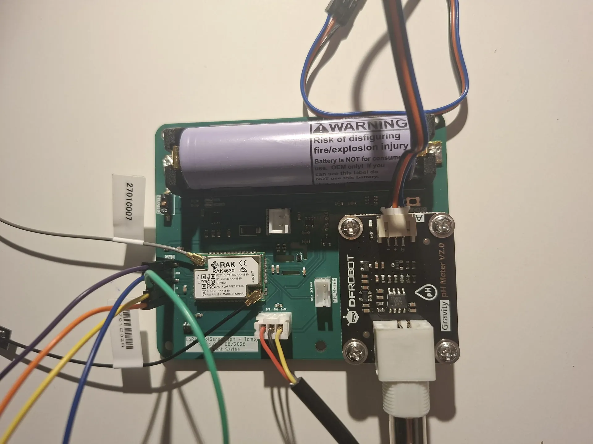
A two layer board that sits by the pool at the house and reports pH, water temperature, air climate and battery. There is no WiFi out there, so the radio is LoRaWAN, with BLE as the path that works until a gateway exists.
The problem
I wanted pool chemistry on the same Home Assistant instance as the house, without running a cable and without pretending the garden has WiFi. Range and battery life matter more than bandwidth. A few bytes every minute is enough: water temperature, pH, air temperature and humidity, cell voltage.
LoRaWAN (EU868) is the right physical layer for that. It also happens to be a gap in my skills. I had already done ESP32 and ESPHome over WiFi on the weather station and the air quality PCB. This board is how I learn the other radio: concentrator, network server, OTAA, the unglamorous parts. BLE is the backup, and for now the only path that is live. If there is no LoRa node yet, a phone reads the UART.
Sensors and power
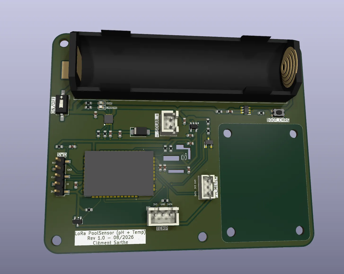
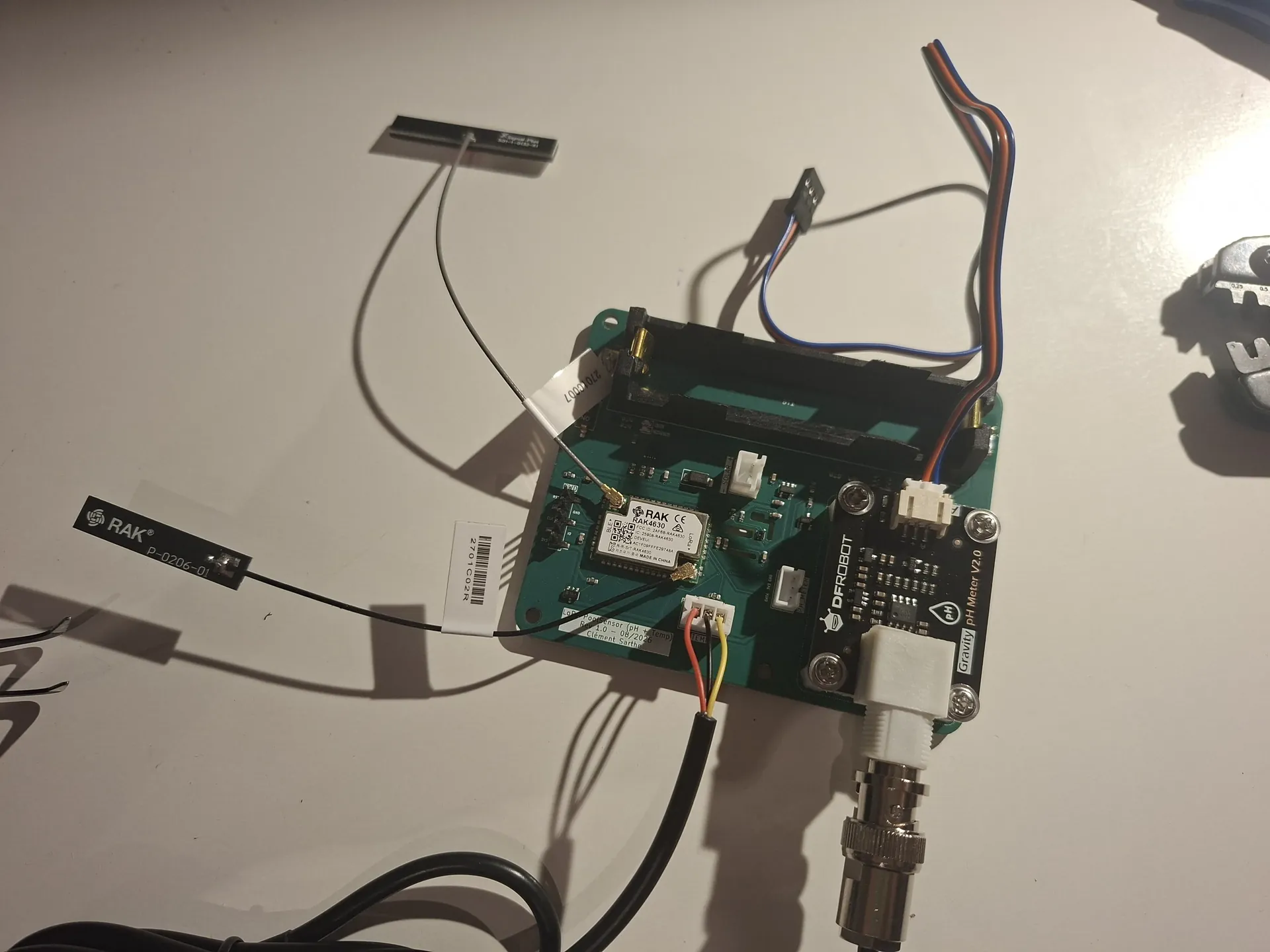
The MCU is a RAK4630-8-SM-I (nRF52840 + SX1262, IPEX). Two MHF1 whip antennas, one for 868 MHz, one for 2.4 GHz BLE. I do not apply power until both are fitted.
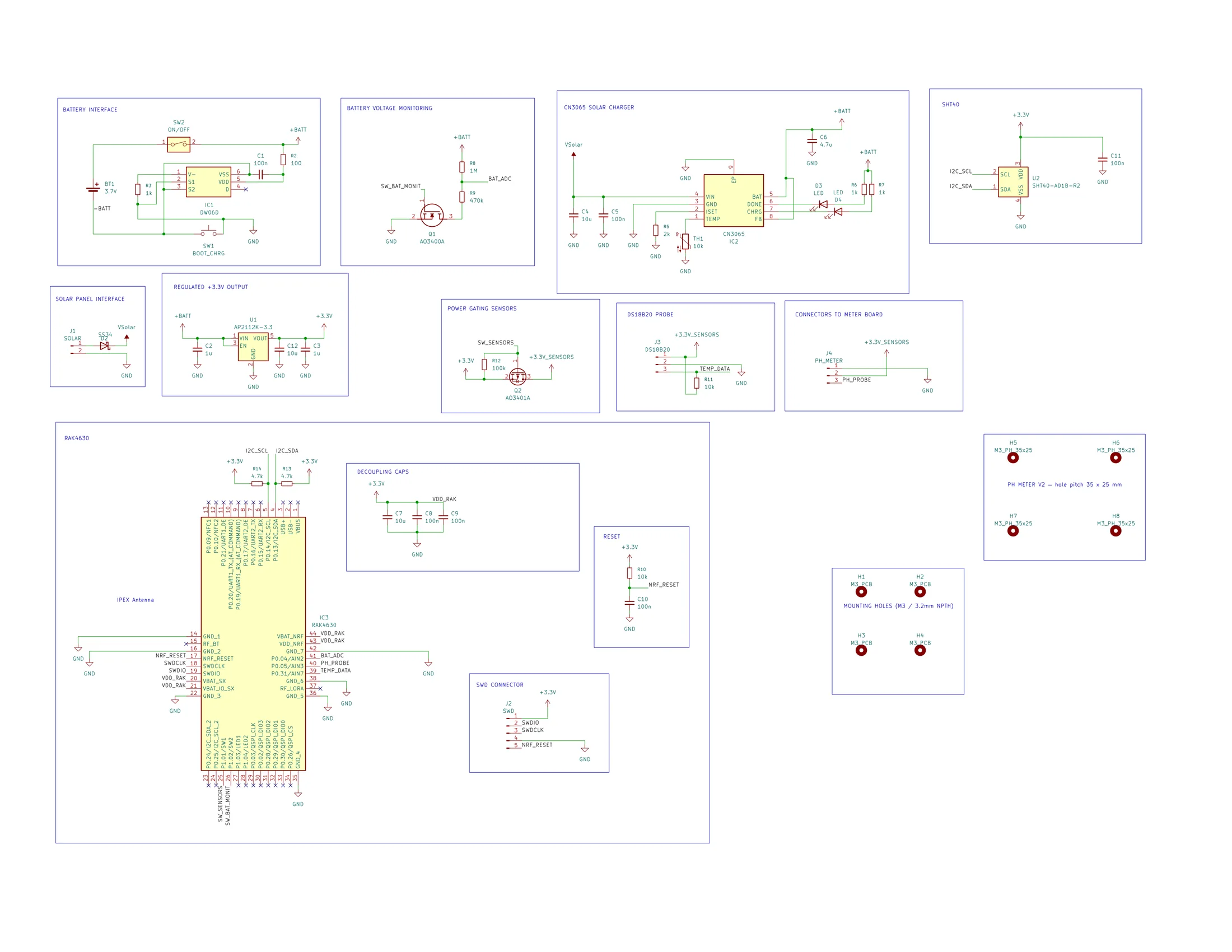
- SHT40 on I2C (P0.13 / P0.14), always on 3.3 V, air temperature and humidity.
- DS18B20 in a stainless probe, Dallas bus on P0.31, VCC switched.
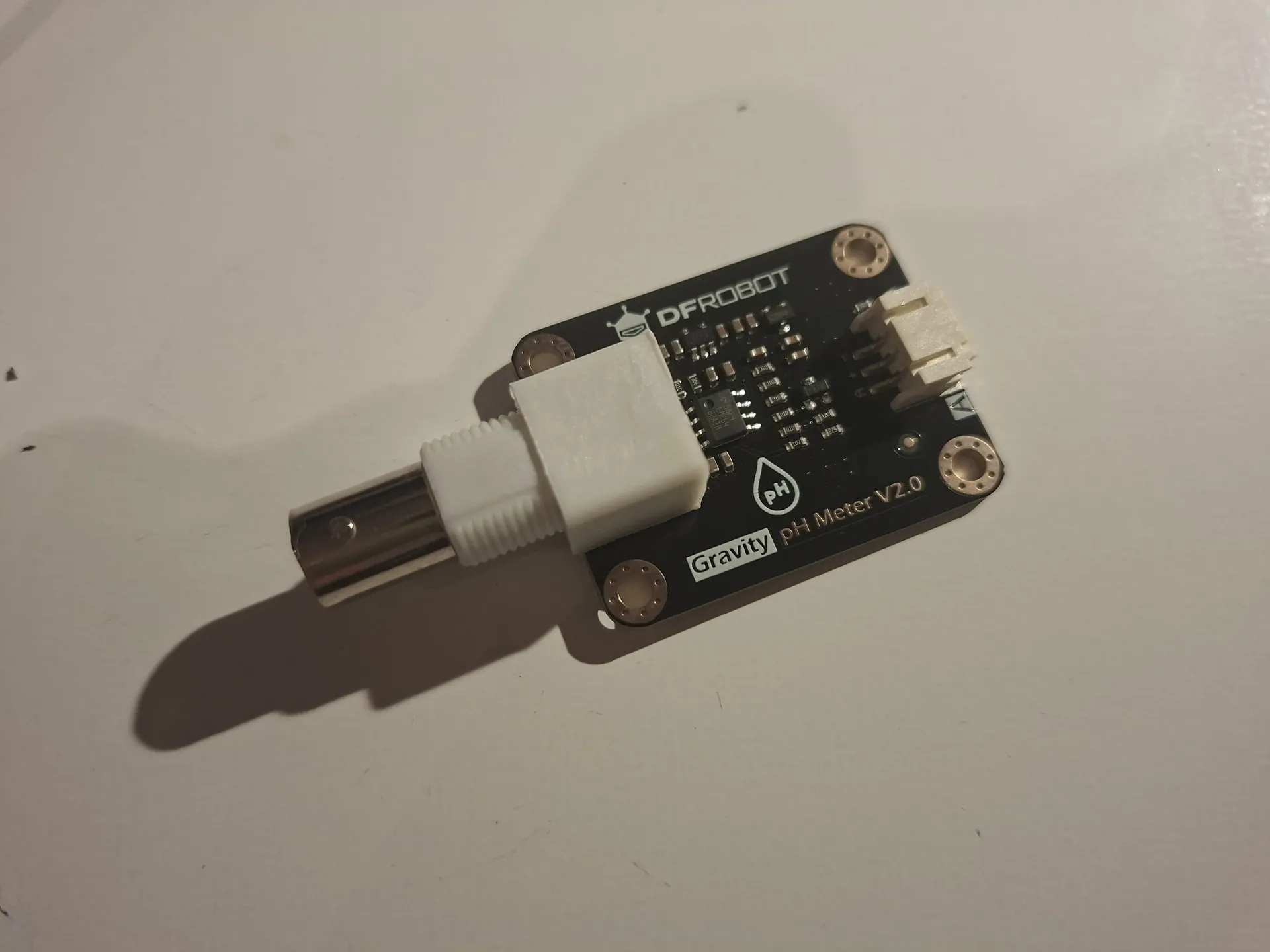
- pH analog on P0.05, through a DFRobot Gravity SEN0161 V2.0 (more on that below).
Power is meant to live outside. The panel is 5 V, 3 W, 10 cm by 10 cm, on J1. An SS34 diode stops the cell from backfeeding the panel. From there a CN3065 solar lithium charger feeds the 18650. ISET is 2 kΩ (about 900 mA on the chip). The panel can only put out about 600 mA at 5 V, so the sun is the real current limit. TEMP is an NTC, CHRG and DONE have their own LEDs. SW2 is the pack on/off switch. A DW06D protects the cell. An AP2112K-3.3 LDO makes 3.3 V for the RAK. A P channel FET (Q2) kills sensor 3.3 V when the node sleeps. An N channel FET (Q1) grounds the 1 MΩ / 470 kΩ divider only while the ADC looks, so the pack is not leaking through that chain all day.
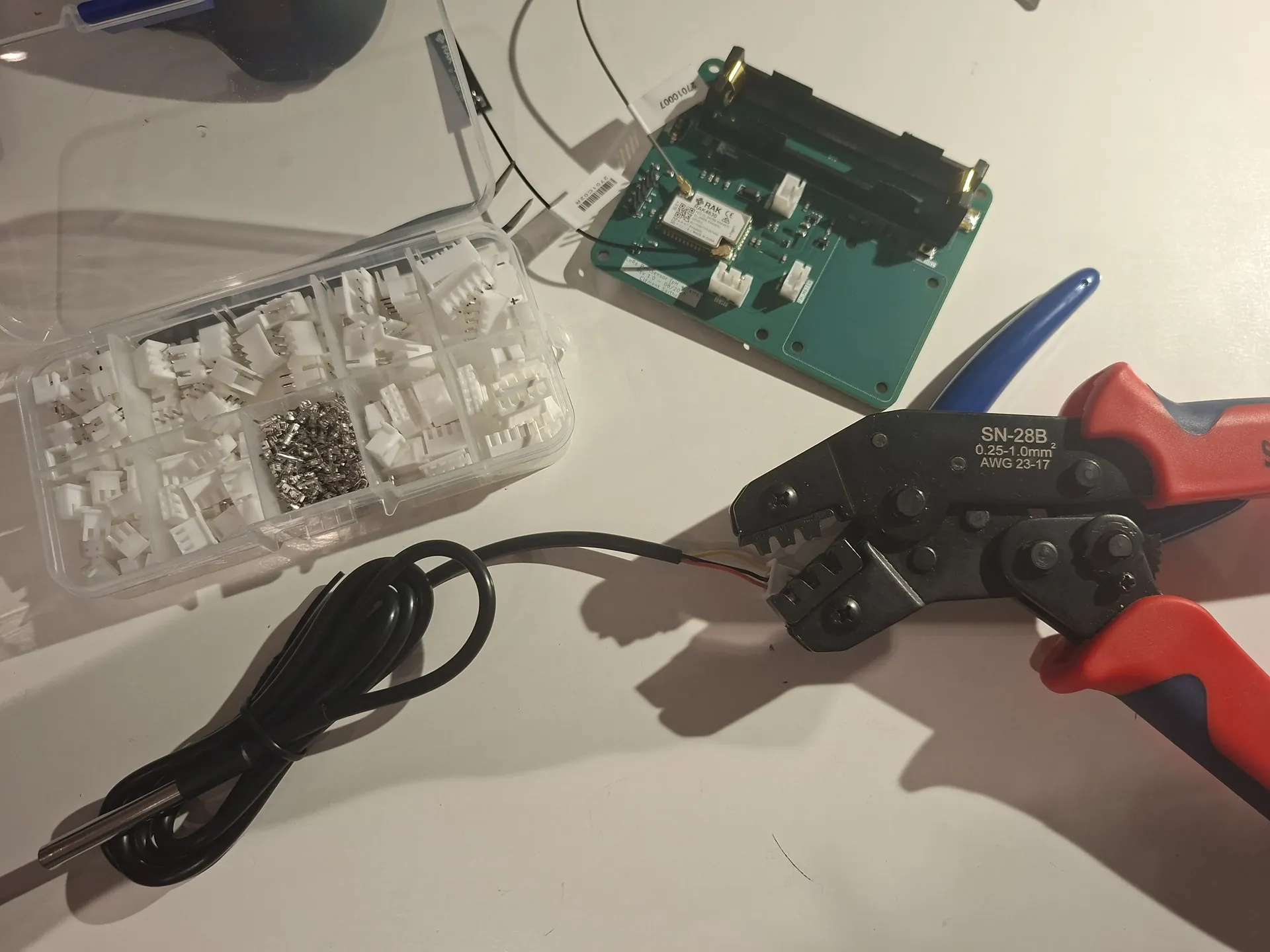
Connectors are JST so the probes can leave the board. Water temp is a three wire crimp (VCC, GND, data) onto J3. I would rather spend an evening on a crimp kit than resolder a probe in the rain.
The pH module I am not proud of
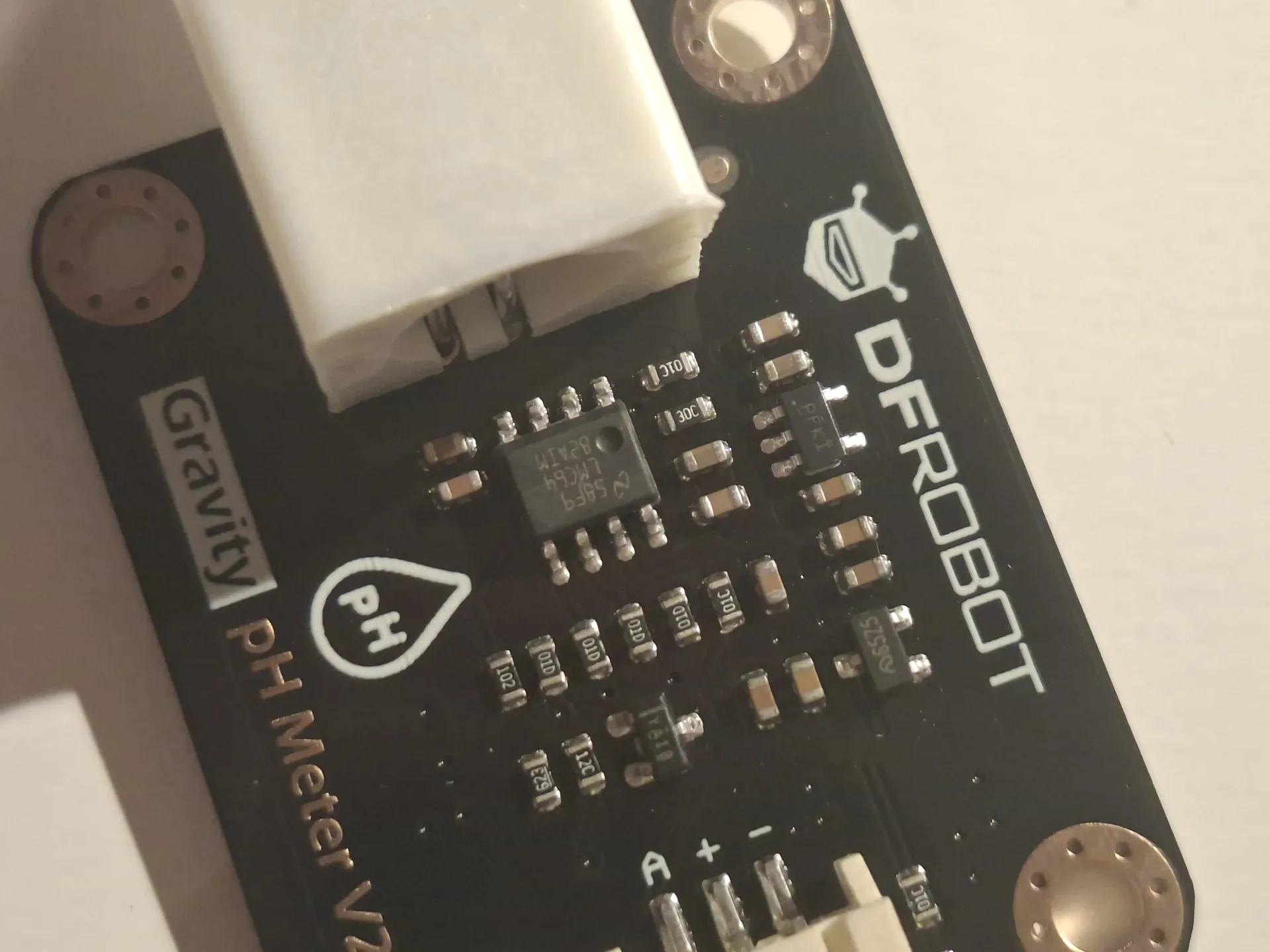
A pH probe is a high impedance glass electrode on a BNC. Doing that analog stage properly means guarding, 50 Ω discipline, and time I did not have. I used the DFRobot Gravity pH Meter V2.0: BNC in, analog voltage out, PH connector on my PCB. It works. It is also the only part of the board I would redo. Next revision I want the BNC on my copper, even if it hurts.
KiCad
Schematic first, then a two layer layout. All signal traces sit on the top copper. The bottom is a ground plane. That is the whole stackup: simple on purpose. The RAK stamp, the 18650 holder, the solar JST and the pH daughter set the outline. SWD is a 1×5 header (J2): 3.3 V, SWDIO, SWDCLK, GND, RESET. USB on the module is not brought out, so programming is a probe, not a cable.
JLCPCB, and the resistor that was not 470 kΩ
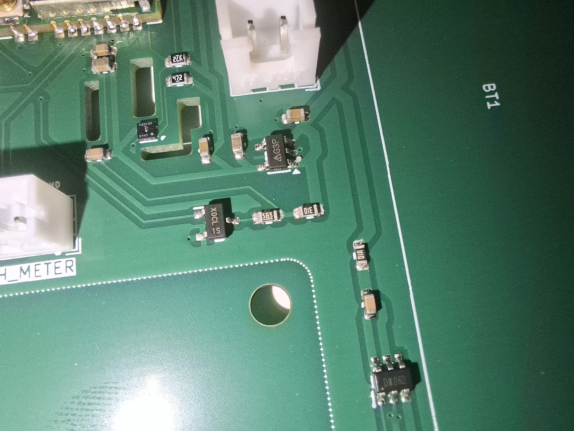
Gerbers, a CPL, and a BOM with LCSC numbers. SMT assembly for everything they can pick; RAK module, holder and connectors by hand. The BOM comment on R9 said 470 kΩ. The LCSC code did not.
C23190 is UNI-ROYAL 0603WAF5604T5E: 5.6 MΩ, marking 565. JLCPCB assembled exactly that, on both boards. The value column is a label. The reel is the LCSC code. With Q1 on, the tap sat at about 3.5 V instead of 1.3 V, close enough to the nRF analog rail to look like the pin was floating, which is the wild goose chase I went on first.
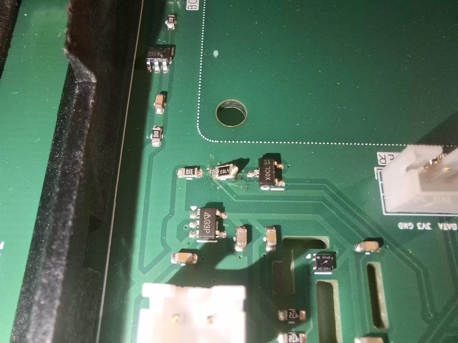
I swapped it for an 0805 470 kΩ I already had. The pads are 0603, so the joints do not look pretty. Good enough: the tap is back at about 1.3 V and the UART tracks the cell.
First power, then data on a phone
Antennas on, then a RAKDAP1 (CMSIS-DAP) on J2. pyOCD, target nrf52840. The probe enumerates as an STM32F103, which is the DAP MCU, not the chip you are flashing. No LoRa gateway yet, so firmware is BLE only: connectable advertising as PoolSensor, Nordic UART, BTHome v2 in the advert for later Home Assistant. SoftDevice S140, app at 0x26000, no USB bootloader. Erase the chip, merge, flash, reset.
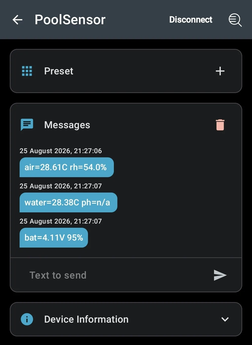
nRF Toolbox on the phone is the whole lab for this phase. One UART line, 60 s, here from 25 August 2026:
air=28.61C rh=54.0%
water=28.38C ph=n/a
bat=4.11V 95%
pH stays n/a until J4 is live. Water needed the DS18B20 actually plugged in. Battery took the R9 swap, then a piecewise 18650 map so 4.11 V is about 95 %, not 88 % of a linear 3.50 V to 4.20 V stick.
Next: LoRa, when the node is up
BLE got me honest numbers without a concentrator. When the gateway is on the bench, the SX1262 on the RAK is the radio that goes to Home Assistant. Plan: a Seeed WM1302 (SPI, EU868) on a Raspberry Pi 4 I already own, ChirpStack as the network server, MQTT into HA. The sensor firmware then grows OTAA and a payload. There is no point debugging air time against a laptop.
That is also the skill I wanted out of the project. WiFi I already know. LoRaWAN, from module to LNS, I did not.
The float
The board is not the finished object. The idea was to repurpose a cheap folding chlorine dispenser that already knows how to float, and turn it into the hull. Electronics in a 3D printed insert, sealed, with only the pH probe, the DS18B20, the antennas and the 10 cm solar panel sticking out. Water stays out. The puck stays in the pool.
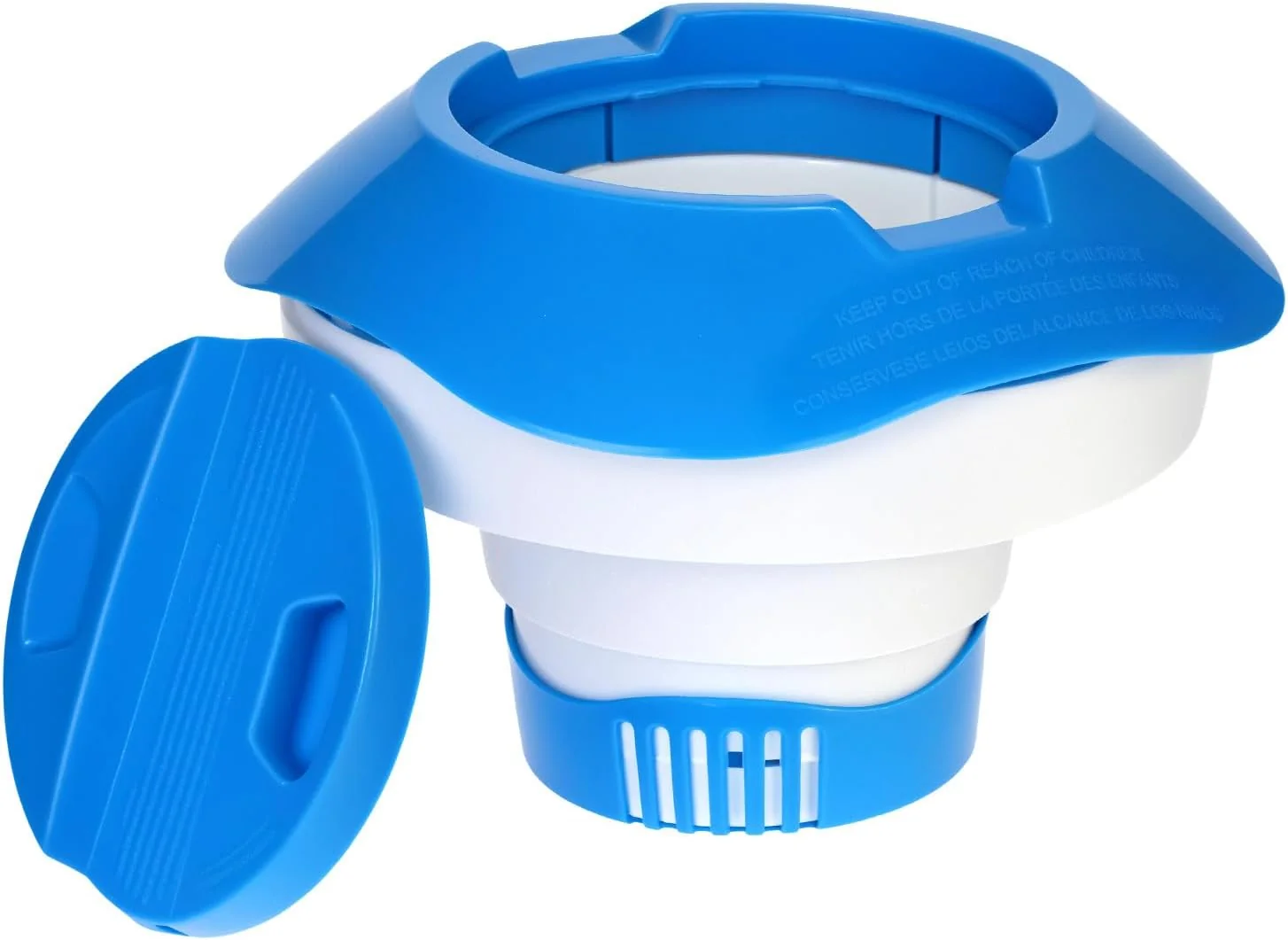
I am moving abroad for work, so that part will not get built on this stay. The PCB and the BLE path are as far as v1 goes.
Where it stands
Two assembled boards. Divider is the right 1 MΩ / 470 kΩ (ugly 0805, but it reads). Phone reads air, humidity, water temperature and pack voltage. pH probe not in the water yet. LoRa idle. Solar unplugged on the desk. The board is a first test that worked, with one BOM lesson I will keep. The float and the gateway wait for another season.
Learnings
The LCSC code is the part. The comment is a wish. A 5.6 MΩ in a 470 kΩ hole still solders, still passes continuity, and still lies to the ADC. Do not invent a BNC analog stage on a deadline. I stand by the DFRobot for v1, and I still regret it. nRF SWD is not USB; flash the SoftDevice or the chip sits in a bootloader you never wrote. BLE is a perfectly good lab instrument when the gateway is still in a shopping cart. And 4.20 V to 4.10 V is surface charge, not 14 % of the cell.